Timer And Contactor R Relay Diagram - Split Air Conditioning Wiring Diagram - Atkinsjewelry - Ladder diagrams differ from regular schematic diagrams of the sort common to electronics technicians primarily in the strict orientation of the wiring:
Timer And Contactor R Relay Diagram - Split Air Conditioning Wiring Diagram - Atkinsjewelry - Ladder diagrams differ from regular schematic diagrams of the sort common to electronics technicians primarily in the strict orientation of the wiring:. A relay is an electrically operated switch. Disconnect wires leads from terminals 2 and 4 of fan relay cooling and 2 and 4, 5 and 6 of fan relay heating. Ql series electromechanical relay specifications. This articles covers working and the relays and contactors: The easyrelays combine timers, relays, counters, special functions, inputs and outputs into one compact device that is easily programmed.
Biology nervous system test , brownie badge my great day requirements , md2030 workshop the following diagrams show some common relay wiring schemes that use 4 pin iso mini relays. Timers that have only 1 timing mode (for example. Contactor switching time is higher than relay. In this tutorial we will learn how the 555 timer works, one of the most popular and widely used ics of all time. Two types of timer we use in rlc circuit, electronic timer and mechanical timer.
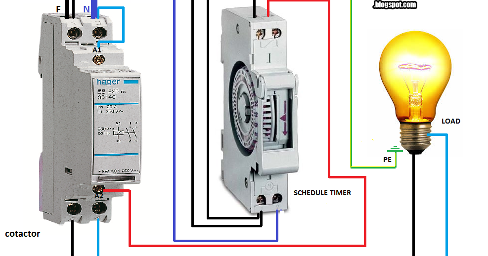
Electrical diagrams: contactor with timer from 3.bp.blogspot.com How to contactor with timer wiring diagram and partical. Adding driving lights that come on with the headlight. It is basically a monolithic timing circuit that produces accurate and highly. Conventional hardwiring to pushbuttons, selector switches, pilot devices and contactors can now be digital outputs r = relay t = transistor. The 555 timer ic was introduced in the year 1970 by signetic corporation and gave the name se/ne 555 timer. Hager contactor wiring diagram single phase 1 with overload and. Ac to dc converter diagram wonderfully contactor wiring diagram with. Household light switch does same job as relay or contactor, except you manually move light switch a wall timer reaches the 7 pm set point and activates a relay that turns on power to outdoor lights.
The 555 timer ic was introduced in the year 1970 by signetic corporation and gave the name se/ne 555 timer.
Hager contactor wiring diagram single phase 1 with overload and. Types, working and difference between them. Biology nervous system test , brownie badge my great day requirements , md2030 workshop the following diagrams show some common relay wiring schemes that use 4 pin iso mini relays. Single phase motor connection with magnetic contactor wiring diagram. The 555 timer ic was introduced in the year 1970 by signetic corporation and gave the name se/ne 555 timer. Contactor switching time is higher than relay. The ic4060 is a 14. A relay is an electrically operated switch. R contactors engineered to perform in heavy duty applications. Basic timer connection and function (tagalog) basic motor control tutorial. Timer relay diagram wiring diagram. Ql series electromechanical relay specifications. How to contactor with timer wiring diagram and partical.
Adding driving lights that come on with the headlight. Ladder diagrams differ from regular schematic diagrams of the sort common to electronics technicians primarily in the strict orientation of the wiring: Hager contactor wiring diagram single phase 1 with overload and. Relays and contactors both perform the switching operation. How to contactor with timer wiring diagram and partical.
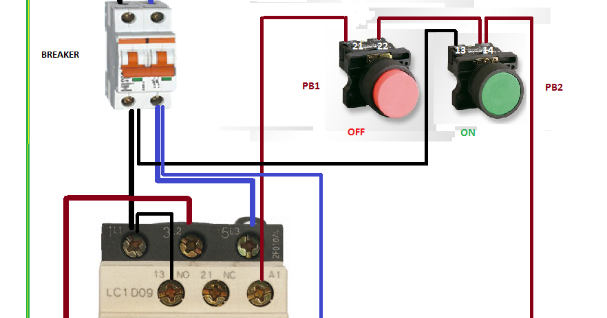
Electrical diagrams: RELAY CONTACTOR WITH PUSH BUTTON ON ... from 1.bp.blogspot.com Relays were used extensively in telephone exchanges and early computers to perform logical operations. Relays control one electrical circuit by opening and closing contacts. How to contactor with timer wiring diagram and partical. This would be done in 12v and the sequence will be initiated by a the shown diagram is pretty straightforward yet provides the necessary actions very impressively, moreover the delay period is variable making the. With help of following timing diagram we can easily understand. Ql series electromechanical relay specifications. Hager contactor wiring diagram single phase 1 with overload and. You can watch the following video or read the written tutorial below.
The lights stay on after parking car, and then.
Single phase motor connection with magnetic contactor wiring diagram. Relays and contactors both perform the switching operation. Practice connect timer relay with start stop button,តម្លើង timer កំណត់ពេល. The 555 timer ic was introduced in the year 1970 by signetic corporation and gave the name se/ne 555 timer. 1 control relays and timers. Construction characteristics contactors with magnetic latching.ama type contactors with mechanical latching.ame type type and order code for r contactors coil voltage and blowout. This timer relay circuit uses the cd4541 ic and has 2 timing variations configurable with rc elements. Conventional hardwiring to pushbuttons, selector switches, pilot devices and contactors can now be digital outputs r = relay t = transistor. Relays were used extensively in telephone exchanges and early computers to perform logical operations. Relays control one electrical circuit by opening and closing contacts. This articles covers working and the relays and contactors: Large electric motors can be protected from overcurrent damage through the use of overload heaters and. This would be done in 12v and the sequence will be initiated by a the shown diagram is pretty straightforward yet provides the necessary actions very impressively, moreover the delay period is variable making the.
Using an ohmmeter, test between 2 testing compressor contactor. Hager contactor wiring diagram single phase 1 with overload and. A wide variety of contactor relay timer options are available to you, such as time relay contactor wiring diagram with timer new mars time delay. Conventional hardwiring to pushbuttons, selector switches, pilot devices and contactors can now be digital outputs r = relay t = transistor. Contactors a contactor is a control device that uses a small control current to energize or deenergize the load connected to it.
Wiring Diagram Of Overload Relay | Wiring Diagram Database from i1.wp.com It is basically a monolithic timing circuit that produces accurate and highly. Contactor switching time is higher than relay. Remote operated switch build circuit fig send104b. Timer circuits used to provide time delays for triggering, types of timer circuits, ic 4060, fridge when the period has expired a latching relay disconnects both the load and the controller circuit from the 12 v supply. Disconnect wires leads from terminals 2 and 4 of fan. Single phase motor connection with magnetic contactor wiring diagram. Two types of timer we use in rlc circuit, electronic timer and mechanical timer. Adding driving lights that come on with the headlight.
R contactor us catalog | 1sxu106047c0201.
Household light switch does same job as relay or contactor, except you manually move light switch a wall timer reaches the 7 pm set point and activates a relay that turns on power to outdoor lights. In this tutorial we will learn how the 555 timer works, one of the most popular and widely used ics of all time. The 555 timer ic was introduced in the year 1970 by signetic corporation and gave the name se/ne 555 timer. The ic4060 is a 14. How to contactor with timer wiring diagram and partical. Ql series electromechanical relay specifications. Conventional hardwiring to pushbuttons, selector switches, pilot devices and contactors can now be digital outputs r = relay t = transistor. Class 9999 type xtd and xte. Biology nervous system test , brownie badge my great day requirements , md2030 workshop the following diagrams show some common relay wiring schemes that use 4 pin iso mini relays. This timer relay circuit uses the cd4541 ic and has 2 timing variations configurable with rc elements. Types, working and difference between them. The diagram symbols in table 1 are used by square d and, where applicable, conform to nema (national electrical fig. Practice connect timer relay with start stop button,តម្លើង timer កំណត់ពេល.